Just 2 photos to give a general idea of the form of the Newport Universal Baseplate.
Just 2 photos to give a general idea of the form of the Newport Universal Baseplate.
In this post we review the MKS-Newport “UP-1A Universal Baseplate.” This is another very useful item to have in your lab. It has applications for testing, measurements, and for tooling. We purchased this product from MKS-Newport at the normal retail price.
Sometimes the pattern of holes on an optical breadboard simply do not work well for your tooling or experiment. In other cases you might not have access to any breadboard. Here is another inexpensive part from Newport which can help to address these situations.
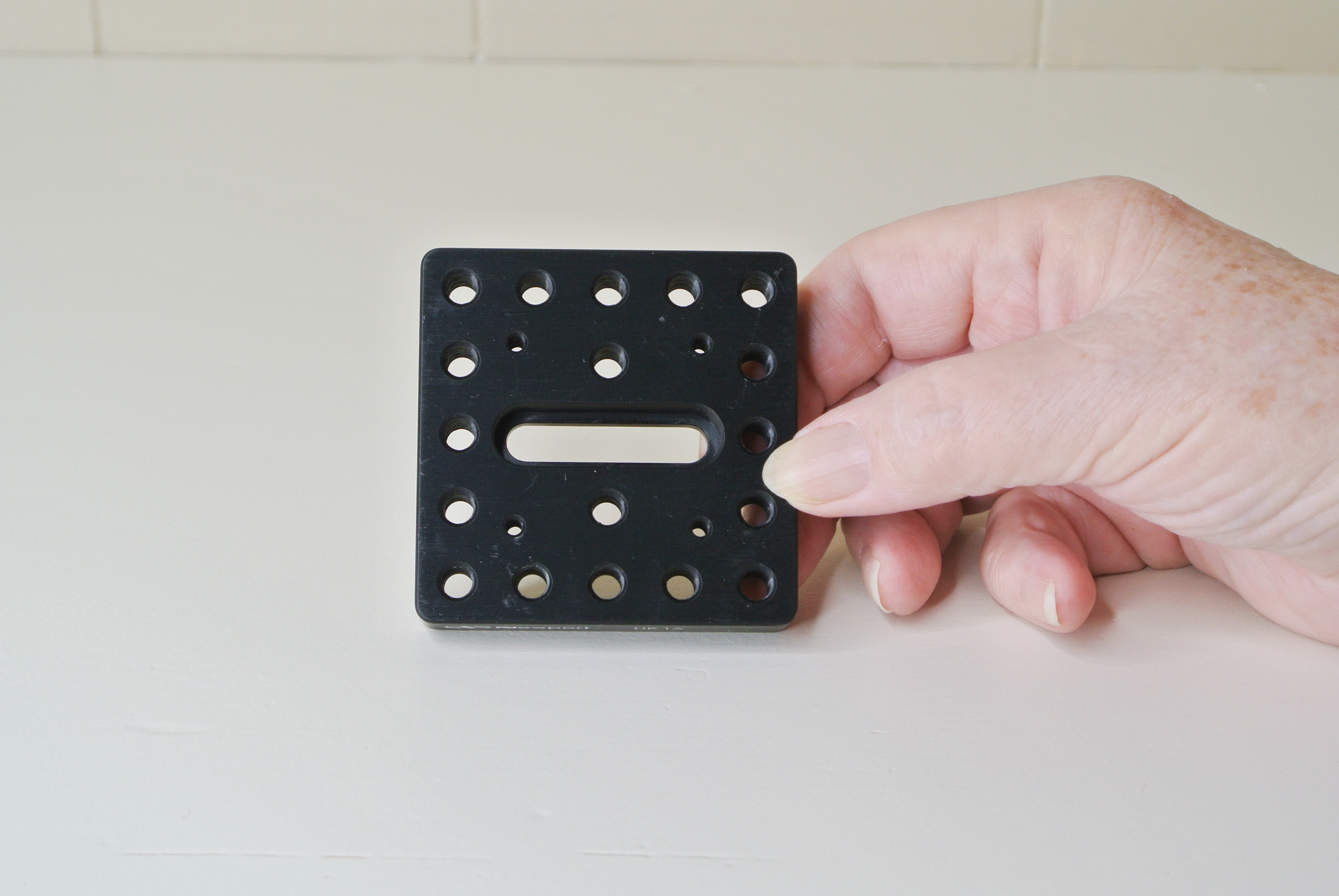
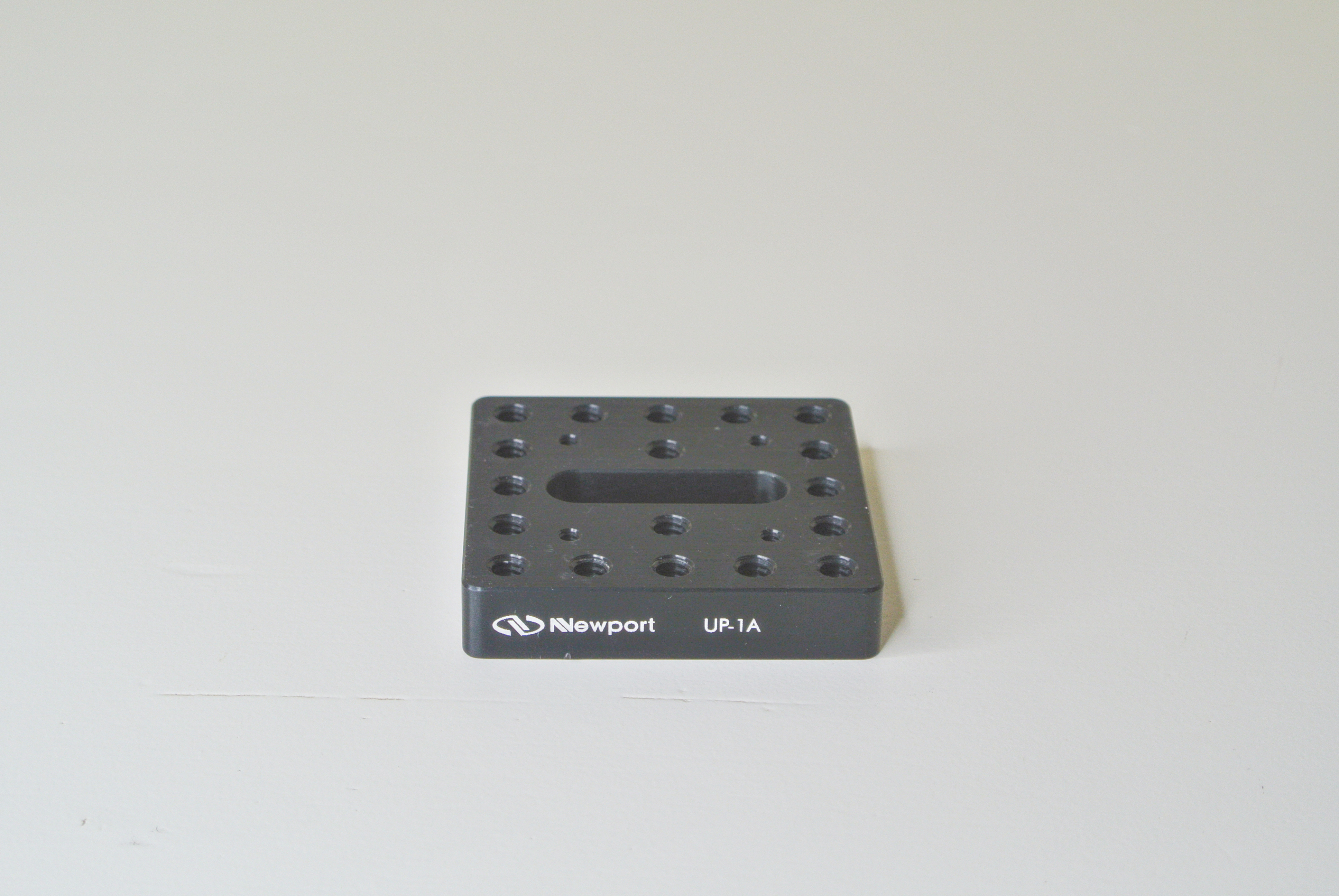
Newport’s model UP-1A Universal Baseplate is a helpful part to have in your opto-mechanical bag of tricks. This item is a small square machined aluminum plate with multiple tapped holes and a slot which is located in the center. It is normally supplied with a matte black surface finish.
It is 2.56″ by 2.56″ and it is about 7/16″ thick. It has an array of 18 through holes tapped with 1/4-20 threads, and 4 holes with #6-32 threads. It also has a central slot which is counterbored, to accept a quarter-20 screw and will clear the head of a socket head cap screw. We will discuss that slot in just a bit.
The UP-1A Universal Baseplate has five 1/4-20 tapped holes along each side of the plate. (The holes in each corner of this plate will count for two sides.) Thus, there are a total of 16 threaded holes around the sides, and these are all spaced on 0.5″ centers. There are two additional 1/4-20 tapped holes in the interior, spaced on 1″ centers, on either side of the slot. That’s a total of 18 holes with 1/4-20 threads through this plate. There are also four holes provided with #6-32 threads spaced on what would be the corners of a 1.25″ square pattern, centered on the plate. Newport describes these holes as being useful for mounting their 40 mm x 40 mm stages. (These items are not described here.)
The Universal Baseplate can be used in a generic way to mount parts for tooling. However, the feature of this design which makes this plate so useful is its central slot. By using a single quarter-20 socket head cap screw to retain the plate to a breadboard, then sliding and rotating the UP-1A as needed before tightening that screw, you can provide a pattern of holes in an arbitrary orientation to the holes in the breadboard. This gives you more flexibility for mounting components than the breadboard does by itself. If you must work without a standard breadboard, you can make the same adjustments on any flat surface when mounting the Universal Baseplate. In this way, you can use this Universal Baseplate without a regular breadboard to provide some quarter-20 tapped holes in various orientations.
This simple but clever design allows an experimenter to move a mounted component around in rotation and (some) translation relative to other components. This freedom of movement can be useful in situations where you might not have established a rigorous spatial design for the equipment you are using, and you are thus searching for the optimal arrangement. It saves a lot of time.
You might wonder why this plate has outside dimensions of 2.56″ by 2.56″. That is part of a clever design. The outside dimensions of this plate are actually 65 mm x 65 mm. This makes the UP-1A Universal Baseplate compatible with the Newport Goniometric stages and their Pitch and Yaw stages, and other devices which also have a 65 mm outside dimension.
Some photos of this Baseplate will be provided in the next post.
END
3 Photos included to provide a general idea of the Construction Plates Product after being assembled to form a bracket.
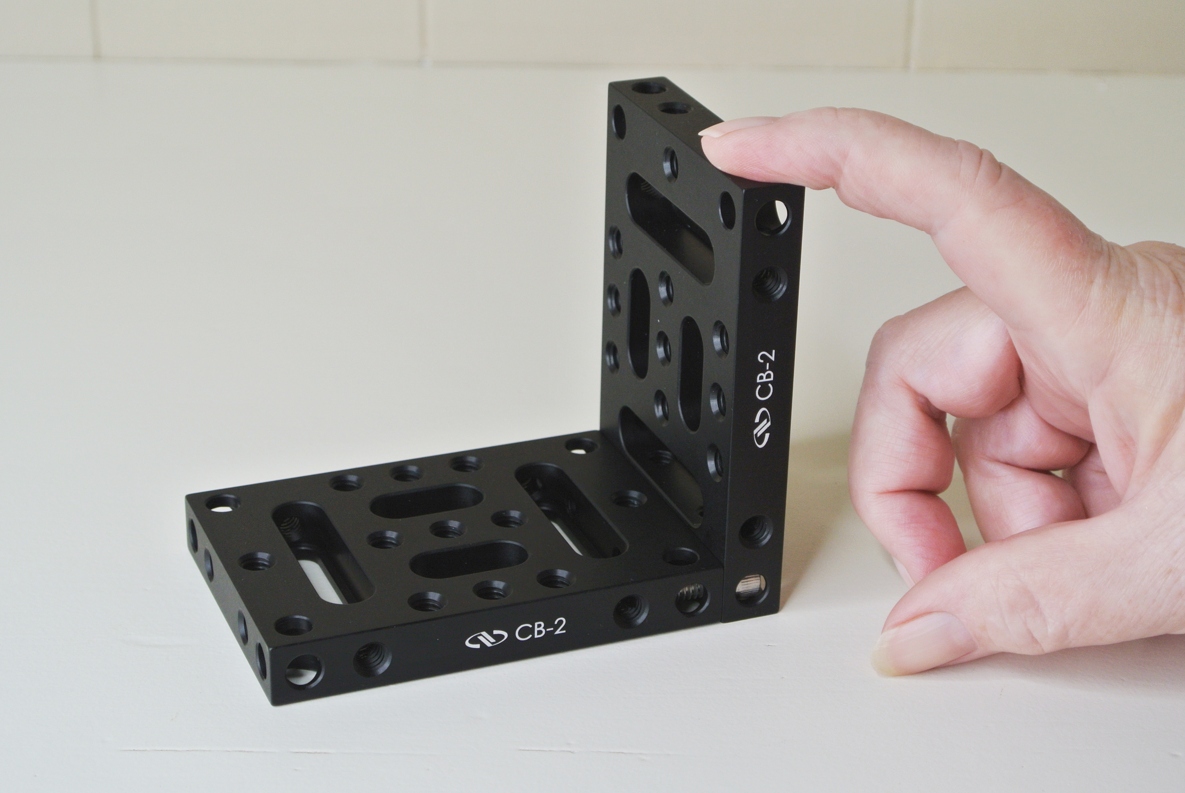
In this post, we describe MKS-Newport’s model “CB-2 Construction Plates.” Newport designates these parts with their nomenclature as CB-2 Construction Plates, 2.5″ x 3.5″, 2 pieces, 1/4-20.
This product consists of two separate but identical aluminum plates, each of which is called a CB-2, and also includes two 1/4-20 socket head cap screws, usually made of stainless steel. We purchased this product from MKS-Newport at the regular retail price.
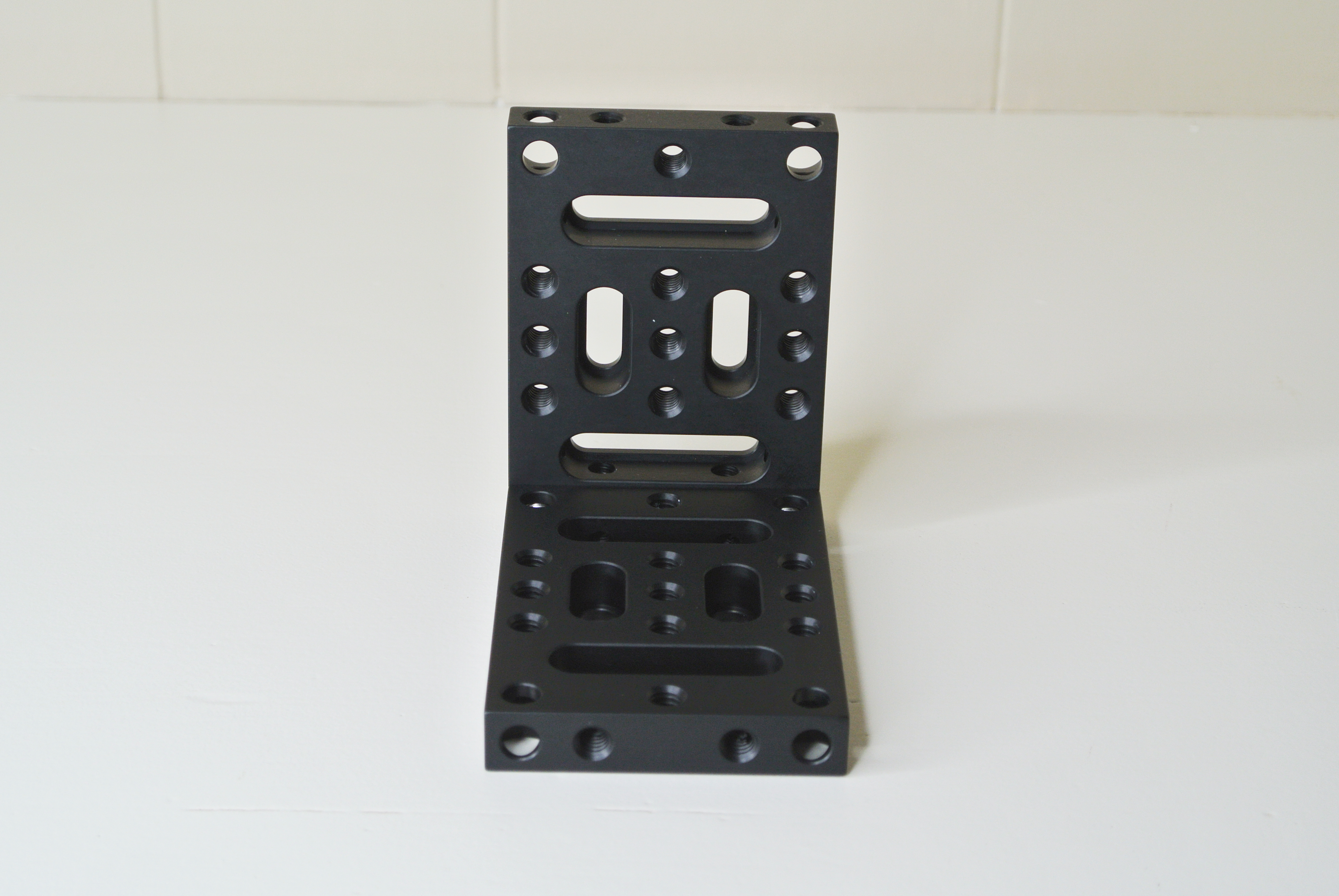
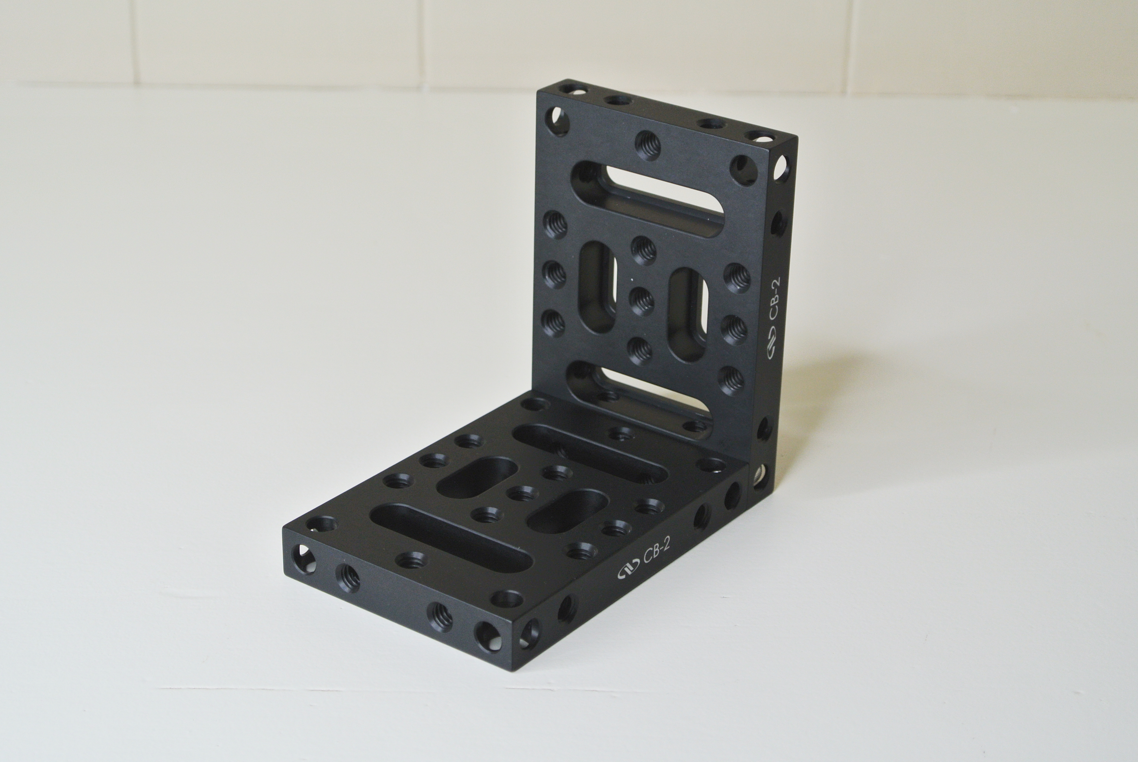
We quote a description of this product directly from Newport’s catalog: (Begin quote) The CB-2 Construction Base is a two-piece design that can be used as a bracket or a base. The base has plenty of tapped holes on all the surfaces as well as clearance holes and slots for 1/4-20 screws. Combine all three elements to construct rigid optical assemblies quickly and easily. (end quote)
The two plates supplied with this product are identical, so we will describe just one of them in detail. This design allows you to use the two plates separately, if that suits your application. They can be assembled together in several ways, as a single device. The CB-2 Plate has the form of a rectangular machined aluminum part.
This Plate from Newport is part of their line of bases. It’s designed to be attached to an optical breadboard or any other part, and has tapped holes on its surfaces so the user can attach other components to it. It is versatile enough to construct rigid optical assemblies without additional machining to the CB-2 itself. Your other components may be custom made. Or, you can assemble these two plates together to make a bracket or other device.
It has outside dimensions of 3.5″ length by 2.5″ width, with a thickness of slightly less than 0.5″. When we measured this sample with an engineer’s caliper, we got the following approximate dims:
3.500″ at the center of the plate, 3.502″ at one end, and 3.502″ at the opposite end for the length; and 2.502″ at the center, 2.501″ at one end, and 2.502″ at the opposite end for the width. We measured the thickness of this plate to be from 2.489″ to 2.490″. (These values are likely within the range of measurement accuracy using a caliper.)
This plate has four counterbored slots to accept quarter-20 socket head cap screws. The two shorter slots are spaced on 1″ centers, and the two longer slots are spaced on 2″ centers. This design means the plate can easily be attached to an optical breadboard having a grid of holes using 1″ spacing. You could use the two slotted holes with 1″ spacing or the two slots with 2″ spacing, and hit the hole pattern in a typical breadboard. The two plates together (minus screws) weighed just under nine (9) ounces.
The two plates in this product can be used separately or together in various ways, by assembling them, which is the reason they include two quarter-20 screws as part of the product.
Each plate has eleven tapped-through holes for quarter-20 screws on the large top surface. The four holes located at the corners of the plate are counterbored clearance holes which allow 1/4-20 socket head cap screws to be installed through each of them, by simply inserting a screw from the counterbored side.
When using this plate as a base, it allows you to attach a component on the top side using a quarter-20 screw inserted from the bottom side. When used as a base, you need only use one of the plates. This means you have the other plate to use as another base or for other purposes in the lab. The counterbored clearance holes at the corners of the plates are useful when making a right angle bracket. Note, there are two ways you can easily combine the plates to fabricate a right angle bracket. The resulting difference just determines where the vertical plate is located relative to the horizontal plate. You can also assemble it and just turn that assembly around to get the result you wish. As another example, you could drill out and counterbore two holes in one of the plates, then assemble the two to create a bracket which is “T”-shaped. Of course you can attach your own custom plate to one of the CB-2 plates, if that is a better result for your application.
This is another Newport product which is convenient and ideal to use with the other parts from their construction series. Of course this base/bracket can be used in many ways with your own equipment for tooling or testing purposes. When assembled to form a bracket, these plates provide a fairly rigid and sturdy component which can be readily used for optical testing applications as well as for custom tooling for assembly and fabrication of small parts. The resulting bracket’s effectiveness may depend upon how heavy your workpiece is going to be.
You could use two (or more) of these assembled brackets to suppkort a larger or heavier workpiece. There are other ways to make a bracket using this product, depending upon your specific application. Often it’s easier or less expensive to use these COTS parts for your application than to order custom designed parts from your machine shop. An engineer or technician could be rewarded by experimenting with these plates for a little while to discover other ways to use the CB-2 Construction Plates.
Some photos of this product will be located in a following post!
End
Some photos of the Newport Construction Rail
Some photos of the Newport Construction Cube
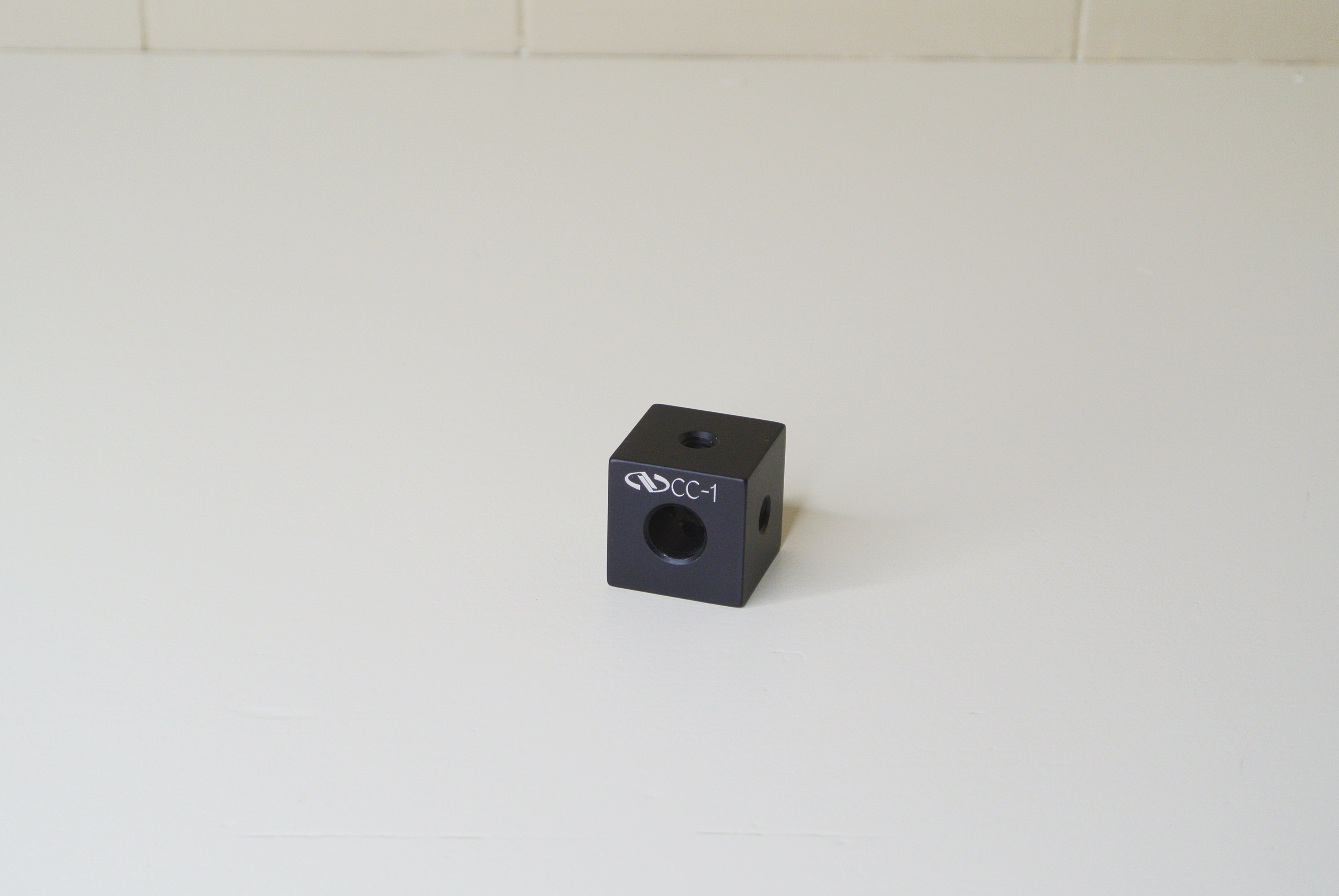
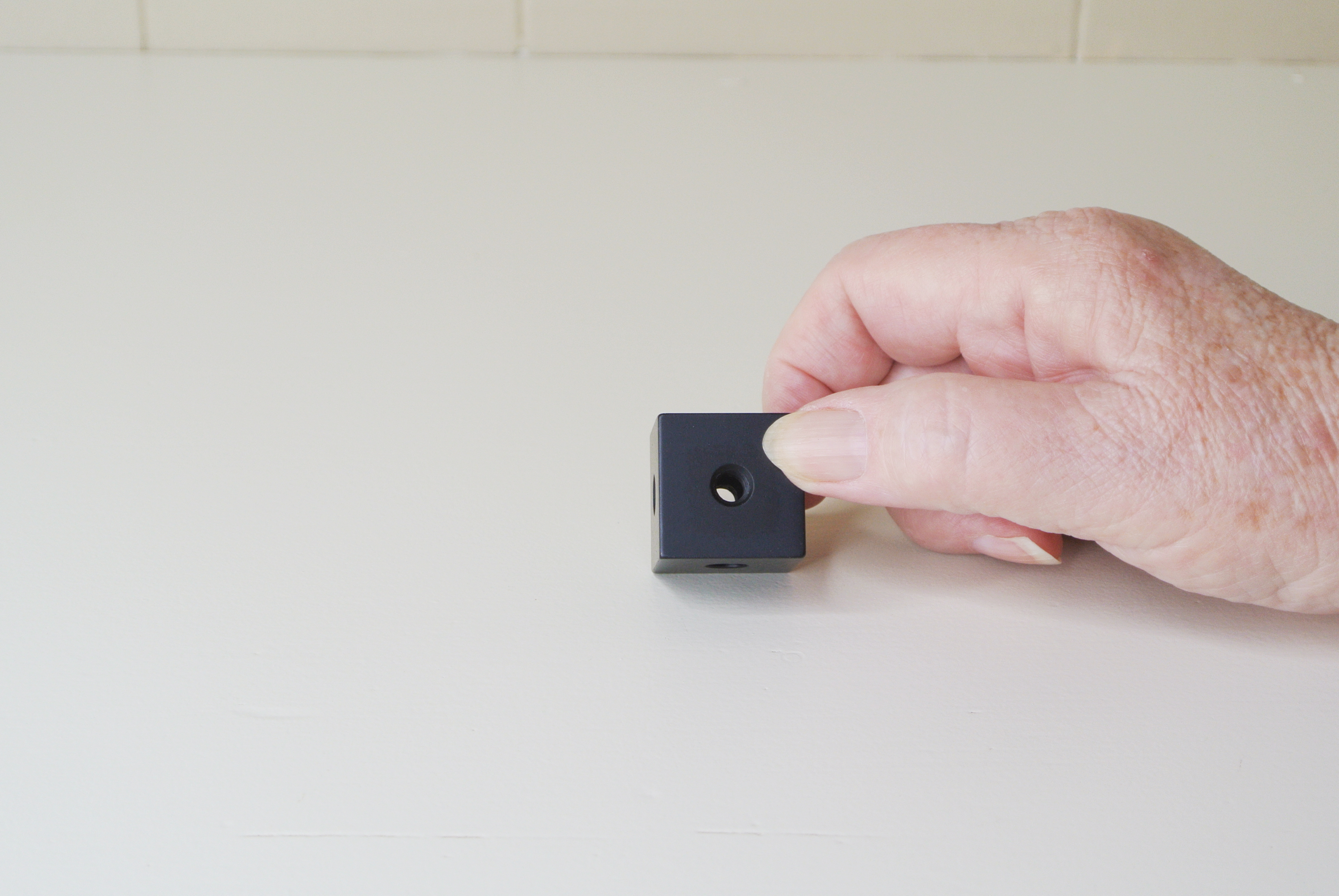
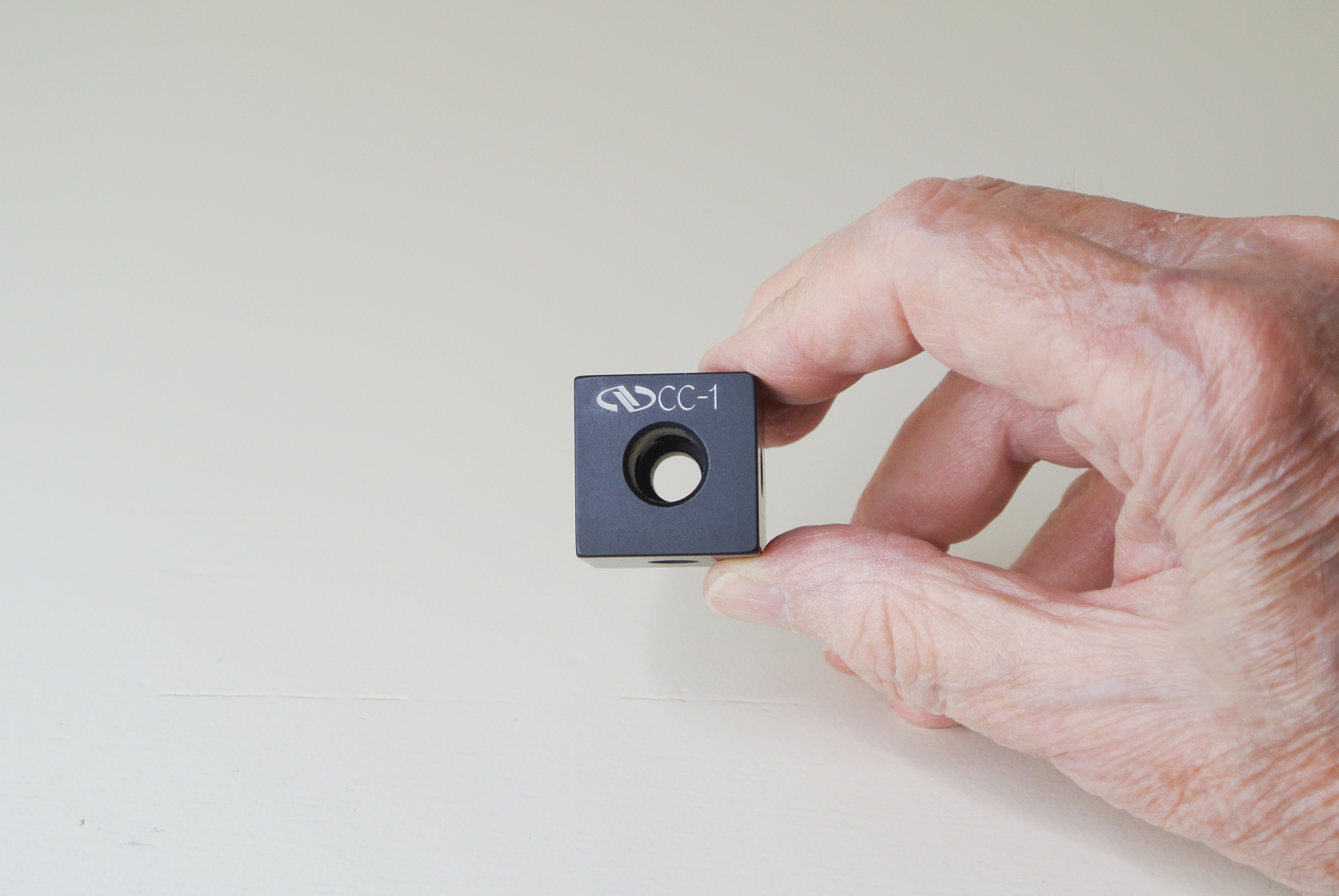
In this blog, we discuss the Newport Construction Cube. Newport designates this part by their nomenclature “CC-1″ Construction Cube, 1″x1”, 1/4-20. This is a machined cube made from aluminum which contains 1/4-20 tapped holes and a clearance hole. It is usually provided with a matte blackened surface.
The Newport CC-1 Construction Cube is made such that it presents six orthogonal faces, being a cube. Four of the faces have one 1/4-20 tapped hole in the center of each face. The remaining two faces of the cube have respectively one clearance hole for a quarter-20 screw and opposite that, one hole counterbored to accept the head of a quarter-20 cap screw. Thus, a 1/4-20 socket head cap screw can be inserted through the cube allowing the user to attach the cube to another external surface.
This design allows the user to attach this cube to another part with a quarter-20 socket head cap screw, where the head of the fastener fits inside the cavity of the cube, out of the way. Then you will have four 1/4-20 tapped holes (in four quadrants) available for other uses. The Construction Cube is simple but quite versatile.
It can be used by itself or attached to your own custom components to construct tooling. When attached with a single 1/4-20 socket head cap screw, it provides a sturdy, rigid component for mounting other parts. It’s especially useful when used with other parts from the Newport construction series.
One note about attaching this cube. With a standard quarter-20 socket head cap screw in the clearance hole, the head of the screw limits the length of screws you may attach to any of the four tapped holes. If instead, you use a low-profile-head type screw, and these are readily available from commercial sources, then a quarter-20 screw inserted into the side of the cube may be a bit longer.
Here are a few examples of really simple ways we used the Construction Cube at work:
1. We used the cube as a simple stop block.
2. We made a simplified adjustable stop block using a quarter-20 cup-point setscrew on one side and a nut to lock the setscrew in place after the desired stop position was set.
3. Two cubes were attached together with one screw to make a spacer for a tooling application.
4. We attached a cube to a construction rail to provide an offset attachment point for another component which we did not wish to attach directly to that rail.
5. Two rails were set parallel with one or 2 cubes used to provide a one inch separation between those rails.
6. Cubes were used to support a flat plate above a breadboard.
Obviously, there are many possible ways to use the cubes in the lab with applications limited only by your imagination. You may want to keep a bunch of these cubes in your assembly parts cabinet.
End
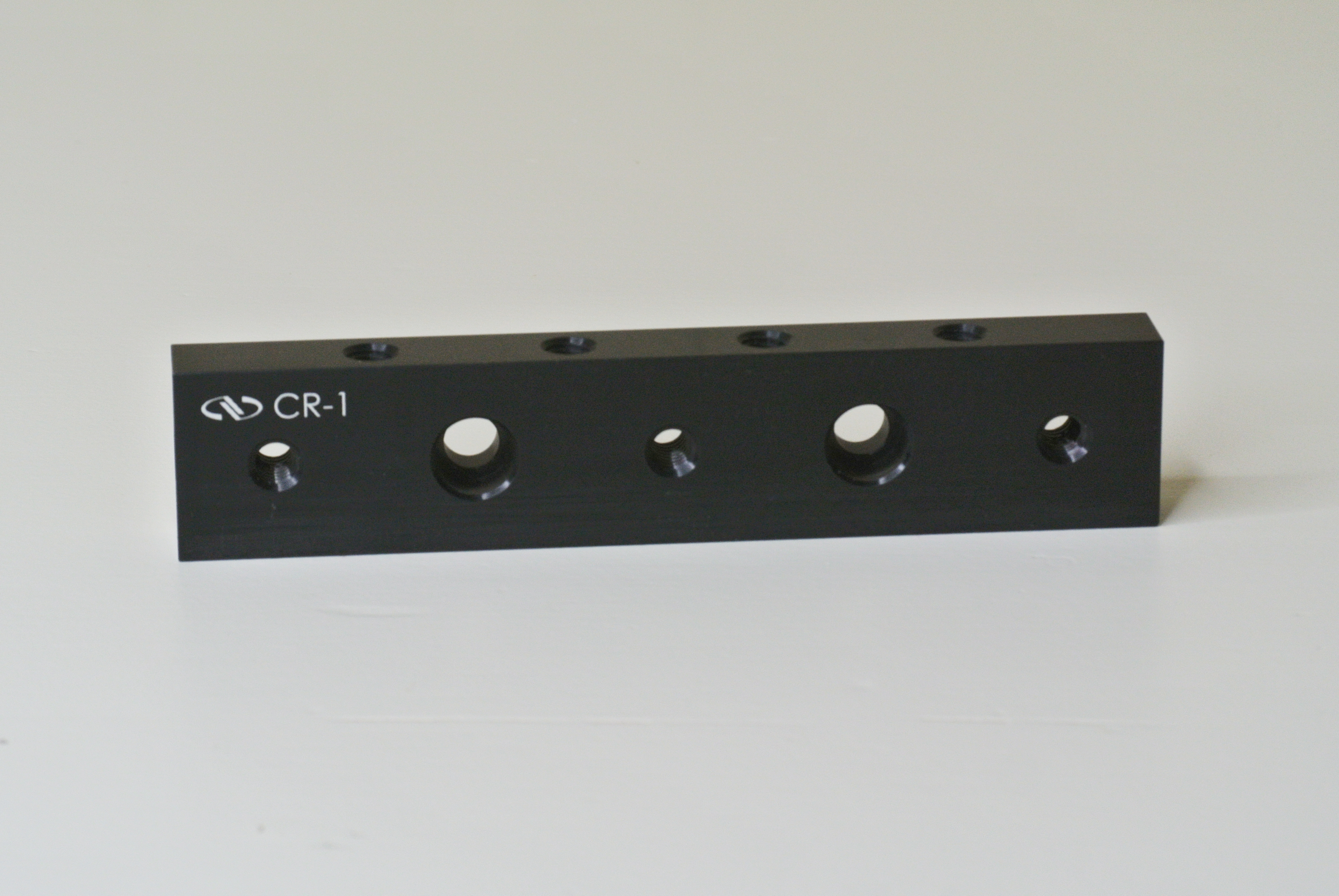
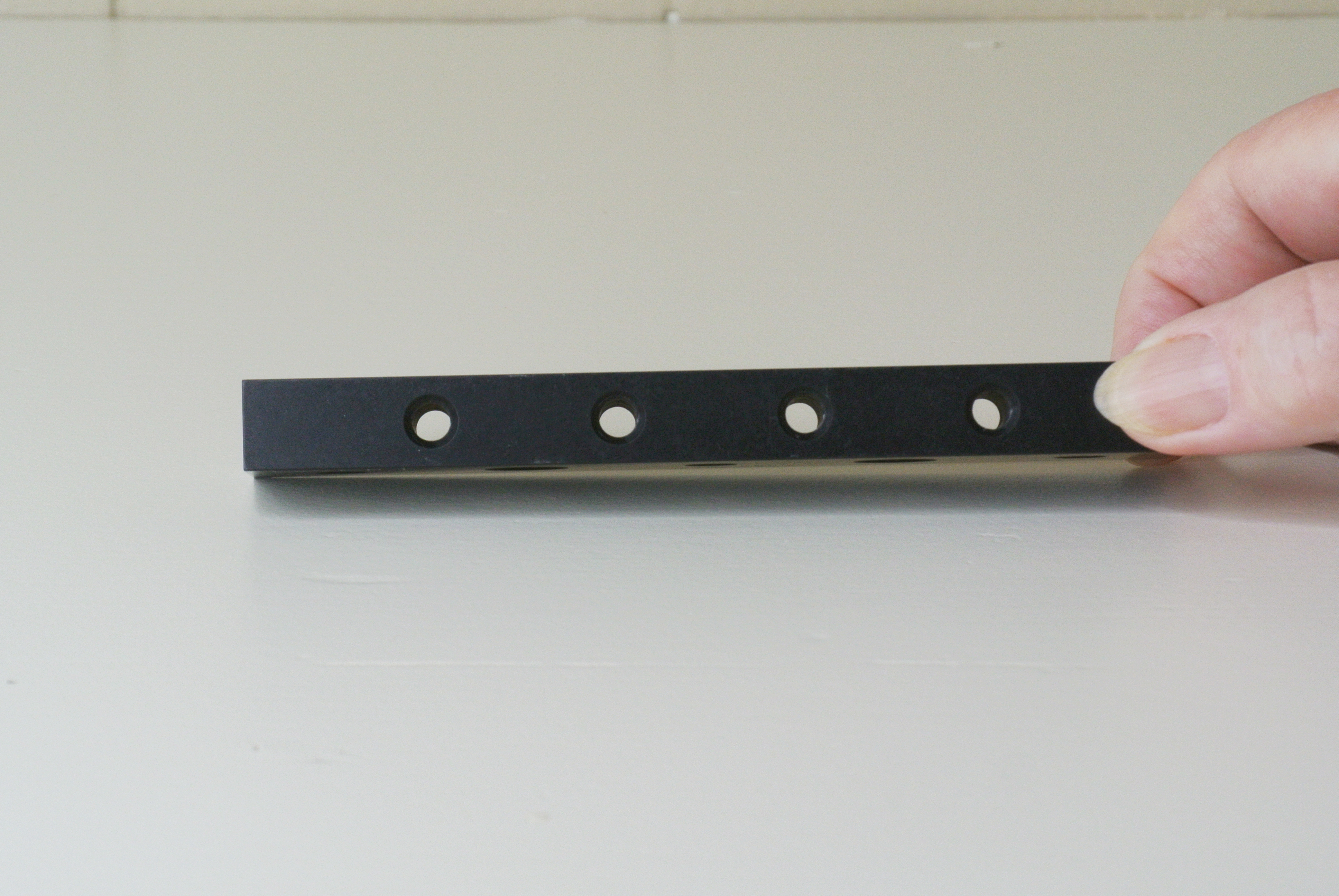
In this post we shall examine the Newport Construction Rail. This is a rectangular aluminum rail with several 1/4-20 tapped holes and two clearance holes for a 1/4″ fastener, with counterbored clearance for the round heads of cap screws. MKS-Newport specifies this product by their nomenclature, “CR-1″ Construction Rail, 1″ x 5”, 1/4-20. Next we will describe these in detail.
Incidently, the rails I will be reviewing are the Revision 2 of the CR-1. This Construction Rail is machined from a solid piece of aluminum. Overall it is a rectangular aluminum part with several holes, some of which are tapped with 1/4-20 machine threads. We did a quick measurement with an engineer’s steel rule which indicated that it is 5″ long, about 1″ wide, and a bit under 1/2″ thick. The part has two clearance holes for a 1/4″ fastener, spaced 2″ apart and about 1.5″ from each end of the rail. It has three each, 1/4-20 tapped through holes in the 1″ wide face. It has four 1/4-20 tapped through holes in the 1/2″ wide face, and also has one 1/4-20 tapped hole in each end of the rail. It normally is supplied with a matte black finish.
The holes are tapped fully through the body of the rail, except for the holes in each end. This is a useful feature if your application requires installing a long screw through the body of the rail where you want it to protrude from the other side for some attachment purpose. As for the two clearance holes, their counterbores are machined so that the head of a standard quarter-20 socket head cap screw will fit within the rail, so the head of that screw is flush with the surface. As for the two holes in the ends (one in each end) of the rail, a standard quarter-20 screw will enter the holes for about 8 and 1/2 turns, if there is no screw located in the last hole in the perpendicular face. If there is a screw in that last hole, then the end screw will enter for about 6 turns, which should be adequate contact for fastening strength for a quarter-20 threaded machine screw.
The three tapped holes in the largest face of the rail are spaced 2″ apart from each other, with the middle hole in the center of the rail. The four tapped holes in the top and bottom of the rail are spaced 1″ apart. When we measured this rail with a machinist’s digital caliper, we obtained the outside dimensions of the part to be:
Its length = 5.001″, its width = 1.002″, and the thickness = 0.490″.So these measured dimensions are very close to the manufacturer’s specified nominal dimensions for this part. That was satisfactory.
We weighed our sample of the Construction Rail with an analog scale just to satisfy curiosity. We obtained a weight of approx. 3.5 ounces.
The Newport Construction Rail was designed to be very adaptable to make various mechanical assemblies. It is just that. This rail can be attached to another rail (or two), or to one or more of the other components we shall review later. The rail is especially convenient for being used with the other construction components made by MKS-Newport.
It can be attached to a conventional optical breadboard surface in various ways. It can be used with other custom built parts you require, or it can be used as part of a custom testing application, as well as to build specialized assembly tooling. Its rectangular shape, strength, and multiple holes for fasteners make this an ideal component for constructing a wide variety of equipment, for optical or other sorts of engineering projects. As mentioned previously, we have experience using these construction rails in applications for building optical instrumentation on large telescopes and also for manufacturing tooling. The Newport Construction Rail has many possible uses in terms of making mechanical hardware in the laboratory as well as in manufacturing plant applications. We know this from actual experience, having actually used these rails to construct tooling in an optical lens manufacturing facility.
End
This post is rather short. Here is a preview of what is appearing next in this blog.
We will be reviewing four opto-mechanical components which are products made by MKS-Newport and are available from their website store. These components can be used separately in many ways, or they may be combined with one another to suit different applications. They are all passive opto-mechanical parts (strictly mechanical) and are made of aluminum and built to high quality standards. We have actually used these parts for multiple tasks in both industry and observatory settings, so we have confidence speaking about them and recommending them. They are known by the following names:
A “Construction Rail,” a “Construction Cube,” “Two Construction Plates,” and a “Universal Baseplate.” They have been around for quite a long time, thus some readers may already be aware of them or have also used them. We shall review each part in a separate post, for convenience. These components are recommended for building tooling equipment and also for testing and calibration applications. Arriving soon.
I have not written many reviews on this blog. I’m working on a full video review of a piece of optical lab equipment, but this is time consuming. In advance of completing a full scale video, I thought it might be of interest to provide some of the text from that review. If someone reads this blog, they might get some useful information about this equipment. So, here we go.
Folks doing optics in the lab often get to use a large breadboard or optical bench with a repetitive hole pattern on the top. That’s fine if you are lucky enough to have one of those benches. In some situations, you might not have access to such a breadboard. You may wish to obtain a small breadboard for experimental or tooling purposes. We will discuss a component which we found to be very useful for those situations where a large optical breadboard or bench is not needed or is just not available for our use.
This equipment is available from Base Lab Tools Inc., a company located in Stroudsburg, Pennsylvania. They are a USA based company specializing in optical breadboards, opto-mechanics, and other products for the optics lab and manufacturing market. For the sake of full disclosure, we have no special connection with this company, other than simply a retail customer. Base Lab Tools did not provide this part for a review; we purchased it at normal retail price. They have a website, from which parts can be ordered. The product we discuss is their model SAB0612-D aluminum optical breadboard. It is 12″ long, 6″ wide, and is 1/2″ thick. It’s blackened on all surfaces and has rounded corners for easy handling. It is a double-density type of board with 1/4-20 tapped through holes on a 1″ spaced grid, but it also has a second grid of 1/4-20 tapped through holes spaced at 1″, but which is offset by 1/2″ from the first set of holes. (This is a common layout for tapped holes and other vendors use it as well.) You can see this layout on their website. I just looked up their website and they are doing business; see http://www.baselabtools(dot)com.
Before continuing with a review, we will comment that it is understandable that this optical breadboard is fairly small, compared with large table-based breadboards used in industry; yes we get that! So if you need a “large” work surface, whatever that may be, then this item may not be what you need. This plate can also be used in connection with a large optical table.
The hole arrangement on the 12″ x 6″ breadboard provides a total of 127 through holes in the plate. Of these holes, 122 are tapped with 1/4-20 threads, while five (5) of them are counter-bored clearance holes for 1/4″ screws for purposes of mounting this breadboard on another plate or on some sort of feet. One of these holes is located near each corner, and one in the center of the plate. Of course you can always drill and counter-bore more of these holes if you need additional clearance holes. We weighed this plate on an analog scale, and got a weight of three pounds and four ounces (3 lb 4 oz). That is clearly light in weight and easy to handle or adjust on another surface. If you needed to adjust it to be level, this should be an easy task due to its light weight.
It is advertised as made in the USA. When we ordered this breadboard from Base Lab Tools in 2022, the retail price we paid was $122, which we consider to be relatively inexpensive for this component. Your opinion regarding cost will depend upon your budget.
We find that this breadboard with the double density hole pattern is very useful for small tooling jobs or experimental setups, when you do not require a long optical path or a large surface area to work on. The only downside you might observe is that it is a solid aluminum plate, only 1/2″ thick, and it does not have a honeycomb structure to provide reduction in vibration or mechanical resonance. Honeycomb type optical benches are wonderful but they tend to be expensive. But this is useful for many purposes, and if you can allow a short time for vibrations or a resonance to dampen out, then it can serve well.
As it is only 1/2″ thick, which is thinner than most expensive optical breadboard benches which have a honeycomb structure beneath the surface plate, you need to use short screws to attach components to the top, so they will not protrude below the bottom surface. You can mount this breadboard on feet or spacers if you wish to allow for longer screws to protrude through the plate, or if you need to mount any components on the bottom surface of the plate. Both of the surfaces of the plate are pretty smooth. We did not do specific testing on surface flatness of this plate.
If you need mild vibration isolation using this breadboard, you can try using the vibration isolating pads which are made for use with astronomical telescopes, which usually are placed under three tripod legs. These are available from retail vendors who sell telescopes and tripods. These might help. Of course, if your work requires interferometry, you will need to use some serious vibration isolation techniques.
We used this breadboard plate for some simple optical experiments. The 1/4-20 threaded through holes in their double density pattern allow one to attach opto-mechanical components via 1/4-20 screws in ways that allow these parts to be located relatively close to each other, if that is what you need. Your experimental or tooling projects could of course be very diverse from ours.
In one simple example the SAB0612-D optical breadboard allowed us to support a Newport model VPH-2 (2″) No-Slip post holder and a steel post holding a Newport M-PPF50 spring loaded Filter Mount. In this case, that Filter Mount was offset from the post by using a short aluminum piece cut from a Newport Construction Rail. The post holder has a 1/4-20 hole in its base for mounting. We used a 1/4-20 stud to mount it to the breadboard to eliminate a screw protruding from the bottom. The assembly supported by a post allowed us to rotate the Filter Mount to set any arbitrary angle in azimuth orientation. We also used it to support a flat mirror in a tip-tilt adjuster mount. Obviously these were simple examples of an application.
One could mount this breadboard on another stable surface for doing optical testing or alignment tasks on small optical systems. It seems to lend itself to lab setups of optics which would fit within its surface area, i.e. 12″ x 6″. We measured the distance between the centers of the tapped holes at each edge of the plate, for the length and width, with a K&E Paragon draftsman’s ruler. For these dimensions we got (approx.) 11″ for the long dimension and 5″ for the narrower dimension. The linear hole-to-hole spacing is one inch. This indicates how you could easily fit equipment on one surface. It’s also possible to mount two of these breadboard plates parallel to each other with spacers, which then gives you four flat surfaces on which to mount equipment.
We have working experience making tooling in an optical manufacturing facility, so we evaluated this breadboard plate from the point of view of tooling applications. It was our opinion that this product would be quite useful for various tooling purposes, especially because it is small and not heavy. As it is made from aluminum, it is stiff, light weight, easy to machine, and non-ferro-magnetic. It should be good for assembly tooling and testing applications.
We hope this information will be useful to some readers who could use a small optical breadboard.
This commentary might be aimed at engineers but it would apply to all humans. Because, as we are all human organisms, all of us are together in the same boat, as we inhabit this incredibly thin layer of our planet.
In our daily lives we are required to make many choices, as engineers and in other roles. Our normal tasks at work, at home, or anything else we do as human organisms often do not challenge us to a large degree, and we make our choices as to what to do casually and with minimal thought. These choices are often based on our prior experiences. There are times however when we are pressured or dictated to make a specific choice in our task by our management. (Here you may feel free to substitute any other word for “management” which you feel is appropriate.) Our management sometimes regards us as robots to be programmed for their desired responses and to achieve suitable actions.
Are we robots, or are we good, experienced engineers? I am suggesting that we are truly good engineers. (Here you may feel free to substitute any other word for “engineers” which you feel is appropriate.) I suggest that we inherently know the distinction between what is “right” and what is “wrong” in relation to our tasks.
It will become clear to a thinking human organism when we are placed into a situation where there is a need for choice, and that we, as good engineers, have the responsibility to choose the “right path” to follow for us, in seeking a solution to our task. In my view, we humans, who question our own existence and purpose, who can create things of beauty for no particular reason other than it feels “right”, have implanted within us the understanding of the distinction between what is “right” and what is “wrong.” We have clear access to this distinction. It then becomes a matter of how thoroughly we have been programmed to follow orders. History clearly shows that thoughtless following of orders can be catastrophic and destructive.
Our “company”, just like ourselves only inhabits the same incredibly thin layer of this planet upon which we are all moving, like ants on the ground. If we wish to feel insignificant, simply compare our size to the size of Earth, then compare Earth to our Sun, and our star to our Galaxy. In spite of our insignificance, we have implanted within us the ability to choose what is “right” over what is “wrong.” An amazing gift indeed! I do not suggest rebelling against management. They have a useful part to perform in this play.
I now quote one portion from the “Engineers’ Creed,” adopted by the National Society of Professional Engineers:
“I pledge: . . . . To place service before profit, the honor and standing of the profession before personal advantage, and the public welfare above all other considerations.” When the need for choice is thrust upon us, I trust we shall respond as good engineers, not as robots. Please, as you respond to that need for choice, look to your own soul first, then to your heart, then to your intellect. Ignore the programming. The right path leads to the right outcome.
Do good work!
